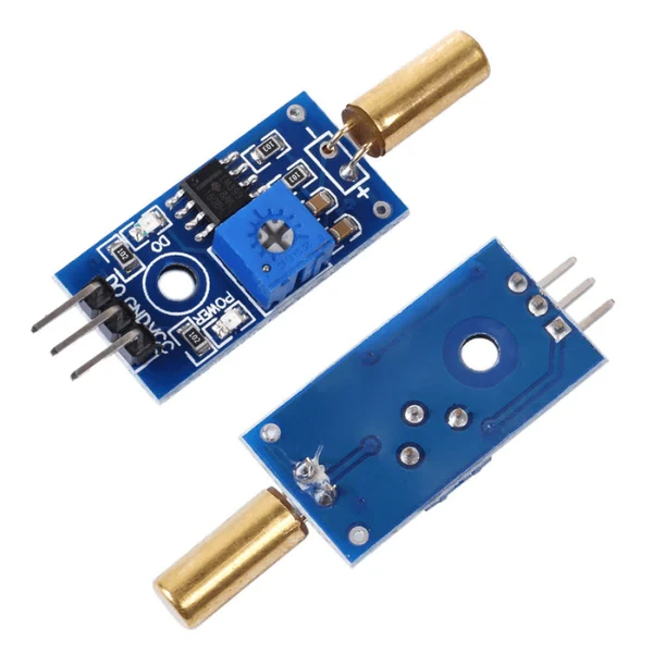

وحدة استشعار الميل / Tilt Sensor Module
(0
المراجعات)
تقدير وقت الشحن:
2 أيام
الفئة
حساسات وموديولات
SKU
1553
منتج داخلي
السعر
12.75SAR
15.00SAR
/PC
-15%
شارك
المنتجات الأكثر مبيعًا
-
0.50SAR
-
1.50SAR
-
0.50SAR
التعليقات والتقييمات
0
out of 5.0
(0
المراجعات)
لم تكن هناك مراجعات لهذا المنتج حتى الآن.
وحدة استشعار الميل هي جهاز إلكتروني يُستخدم لتحديد زاوية ميل جسم أو سطح ما. تتكون الوحدة عادةً من مقياس تسارع أو جيروسكوب أو مفتاح إمالة، والذي يكتشف التغيرات في موضع الوحدة بالنسبة للجاذبية الأرضية. تُستخدم وحدات استشعار الميل في مجموعة متنوعة من التطبيقات، بما في ذلك:
- التحكم في الروبوتات: للحفاظ على توازن الروبوتات وتوجيه حركتها.
- أنظمة الأمان: لتنبيه المستخدمين في حال حدوث ميلان أو انقلاب في المعدات أو المركبات.
- ألعاب الفيديو: للتحكم في حركة الشخصية أو الكاميرا بناءً على إمالة وحدة التحكم.
- التطبيقات الطبية: لمراقبة حركة المرضى أو وضعهم.
مميزات وحدة استشعار الميل:
- سهولة الاستخدام: يمكن توصيلها بسهولة بأجهزة الميكروكنترولر أو أجهزة الكمبيوتر.
- دقة عالية: توفر قياسات دقيقة لميل الجسم أو السطح.
- انخفاض التكلفة: حل اقتصادي لتحديد زاوية الميل.
- صغر الحجم: تجعلها مناسبة للاستخدام في المساحات الضيقة.
- سهولة التركيب: يمكن تركيبها بسهولة على مختلف الأسطح.
مواصفات نموذجية لوحدة استشعار الميل:
- نطاق قياس الميل: -90° إلى +90°
- دقة القياس: ± 1°
- واجهة الإخراج: رقمية (TTL) أو تناظرية
- استهلاك الطاقة: 5 mA
- درجة حرارة التشغيل: -40°C إلى +85°C
المنتجات التي يتم شراؤها بشكل متكرر مع هذا المنتج
المنتجات الأكثر مبيعًا
-
0.50SAR
-
1.50SAR
-
0.50SAR

